Common Solutions to Avoid Issues in Mold Design:
I. Mold Structure Design Issue Avoidance
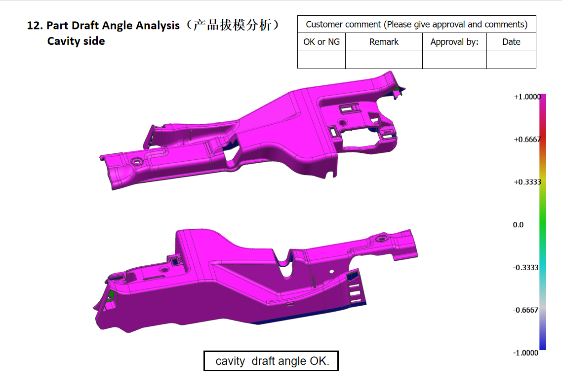
1-1. Unreasonable parting surface design The parting surface should avoid product appearance and assembly surfaces, while ensuring the product can be smoothly demoulded to prevent sticking. Before design, simulate the mould opening trajectory and check for sharp corners or thin edges on the parting surface to prevent issues such as chipping or excessive flash during mold production.
1-2. Defects in demoulding mechanism design The arrangement of ejector pins and blocks should be evenly distributed to avoid excessive local stress that may deform the product. For deep cavity or thin-walled products, add auxiliary demoulding mechanisms (such as push plates or inclined ejectors) and check the ejection stroke to ensure the product can fully separate from the mold cavity after demoulding.
1-3. Insufficient guiding and positioning accuracy The mold’s guide pins and bushings should be made of wear-resistant materials, with sufficient length and fit precision to avoid misalignment or jamming during clamping. For high-precision molds, add positioning pins for auxiliary alignment, ensuring the cavity-core alignment error is within 0.005mm.
2. Mold Material and Heat Treatment Issue Avoidance
2-1. Improper material selection Choose mold steel according to product production volume and material (such as plastic or metal): for high-volume injection molds, prefer wear and corrosion-resistant steels like H13 or S136; for stamping dies, use high hardness steels like Cr12MoV. Ordinary carbon steel should not be used as a substitute for specialized mold steel to avoid premature wear or deformation.
2-2. Substandard heat treatment process Key mold components (cavities, cores, punches) need standardized heat treatment, controlling quenching temperature and tempering cycles to ensure hardness and relieve internal stress. Conduct flaw detection after heat treatment to avoid defects such as cracks or soft spots, preventing edge chipping or breakage during mold use.
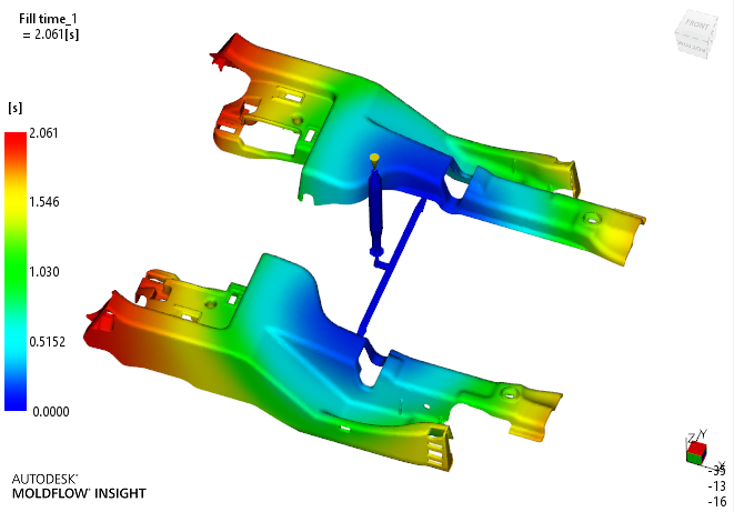
3. Avoiding Design Issues in Cooling and Venting Systems
1-1. Uneven Cooling System
The cooling channels should closely follow the cavity and core surfaces and be designed with parallel circuits to ensure consistent water flow speed across all circuits, avoiding significant local temperature differences in the mould that may cause uneven shrinkage, deformation, or warping of the product. The diameter and spacing of the channels should be calculated based on the product size, and temperature monitoring points should be installed at the inlet and outlet.
1-2. Clogged or Insufficient Venting System
Vent grooves should be provided at the ends of the mould cavities, parting surfaces, and gaps around inserts. The depth of the vent grooves should be less than the allowable flash of the product material (for plastic moulds, typically 0.01–0.03 mm). Prevent grooves from being too deep, which may cause flash, or too shallow, which may hinder air escape, leading to incomplete filling, scorching, or bubbles.
4. Avoiding Issues in Mould Component Machining and Assembly
1. Machining Accuracy Errors
Key components such as cavities and cores should be manufactured using high-precision methods, such as CNC machining or EDM, with strict control over dimensional tolerances and surface roughness. Full-size inspection should be conducted post-machining to ensure conformity with design drawings, preventing dimensional deviations that could lead to product oversize or poor assembly.
2. Improper Control of Assembly Gaps
The fitting gaps of all mould components should be strictly controlled: sliding fits (e.g., guide pins with bushings, inclined guide pins with sliders) should have appropriate clearance to prevent looseness or jamming; fixed fits (e.g., inserts with plates) should use interference or transition fits to avoid looseness or displacement during use. …
5. Avoiding Issues in Product Compatibility and Mold Trial Optimization
1. Ignoring product forming characteristics
Before designing, it is essential to fully understand the forming characteristics of the product materials, such as the melt flow index and shrinkage rate of plastics, or the ductility and springback of metals. Mold cavity dimensions should allow for shrinkage, and the shrinkage rate should be adjusted based on parameters provided by the material supplier and actual trial mold data to prevent product dimensional deviations.
2. Inadequate trial molding verification
After the mold is processed, trial molding should be conducted. Based on defects observed in trial samples (such as flash, deformation, or incomplete filling), adjustments should be made to the mold structure and process parameters. The trial molding should produce at least 50–100 consecutive pieces, and only after confirming stable product quality should mass production be started. It is prohibited to launch production without trial molding.